

4A0-205 Certification Overview - [May 23, 2026] Latest 4A0-205 PDF Dumps
The Best Nokia 4A0-205 Study Guides and Dumps of 2026
Nokia 4A0-205 Exam is a rigorous and challenging exam that requires significant preparation and study. It is designed to test an individual's knowledge and skills in optical networking and requires a thorough understanding of the concepts, technologies, and best practices used in the industry. 4A0-205 exam consists of multiple-choice questions and covers various topics, including optical networking basics, network design, network management, and network security. Individuals who pass the exam will have demonstrated their ability to implement, manage, and troubleshoot optical networks effectively.
NEW QUESTION # 20
What does it take to get connected to the NSP platform?
- A. A browser and the NSP IP address; and from the landing page, the NSP application should be downloaded and launched.
- B. The NSP package should be downloaded from the Nokia website and properly licensed for the specific workstation to be used.
- C. A browser and the NSP IP address. Then, a browser plugin needs to be installed and the laptop rebooted before the NSP can be correctly reached.
- D. A browser, the NSP IP address, and the credentials to access the web-based interface (WebUI).
Answer: D
Explanation:
To get connected to the Nokia Service Platform (NSP) platform, you need a browser and the NSP IP address. Then, you need the credentials to access the web-based interface (WebUI) for the NSP platform. Once you have these, you can access the NSP platform from a web browser.
NEW QUESTION # 21
Which of the following statements about the contentionless feature on a CDC-F node is TRUE?
- A. It represents the ability to reroute lambdas to any direction.
- B. It represents the ability to drop the same wavelength from different degrees.
- C. It represents the ability to support the Fixed Grid standard.
- D. It represents the ability to drop any lambda from any Add/Drop block port.
Answer: B
Explanation:
Comprehensive and Detailed Explanation From Nokia Optical Networking Fundamentals:
The term CDC-F stands for Colorless, Directionless, Contentionless, and Flex-grid. While "Colorless" allows any wavelength on any port and "Directionless" allows any port to be routed to any output fiber (degree), Contentionless solves a specific physical limitation of traditional multiplexers. In a standard ROADM, you cannot drop the same wavelength (e.g., Channel 21) from two different directions (e.g., North and West) into the same add/drop structure because they would "contend" or collide on the same internal fiber.
A Contentionless architecture (typically utilizing a Multicast Switch or MCS) allows the node to drop the same wavelength from different degrees simultaneously without interference. This is critical for high-availability mesh networks where a single transponder might need to receive a specific wavelength from a primary path and a backup path. Without contentionless capabilities, operators would have to carefully manage wavelength assignments across the entire network to ensure no two identical frequencies ever meet at the same drop structure, which significantly complicates planning and restoration.
NEW QUESTION # 22
How does a Raman pump work in the 1830 specific implementation?
- A. As the incoming signal power increase, the gain of the amplifier is reduced.
- B. The pump light travels in the same direction of the signal, amplifying it while it flows in the fiber towards the following node.
- C. The amplification is done simultaneously for all channels as they enter the board.
- D. The pump light travels in the opposite direction of the signal to be amplified, amplifying it while it arrives from the adjacent node.
Answer: D
Explanation:
In Raman amplification, a pump laser is used to excite the Raman-active molecules in the fiber, which then amplifies the signal light as it travels in the opposite direction. In the 1830 specific implementation, the pump laser is typically a high-power laser that is launched into the fiber in the opposite direction to the signal. The pump light interacts with the Raman-active molecules in the fiber, which then amplifies the signal light as it travels in the opposite direction. This allows the Raman pump to provide a gain that increases with distance, which can be used to compensate for the loss of signal power as it travels through the fiber.
NEW QUESTION # 23
What is the meaning of first, second, and third window in the optical fiber propagation context?
- A. These three windows are three different angles of incidence of the light injected by the laser into the fiber.
- B. These windows are three different wavelength intervals where the WDM optical transmission occurs.
- C. These windows correspond to three different minimum and maximum optical power levels used for optical transmission.
- D. Different optical transmission windows correspond to different safety requirements and rules for the related lasers operating with these windows.
Answer: B
Explanation:
In optical fiber propagation context, the first, second, and third window refer to different wavelength intervals where the WDM (Wavelength Division Multiplexing) optical transmission occurs.
The first window is the lowest loss window and is typically in the range of 1300-1324nm. This is the most commonly used window for long-haul communications.
The second window is the 1550 nm window and is the most widely used window for long-haul and ultra-long-haul communications. This window has a lower attenuation than the first window, but it also has more dispersion, which can limit the maximum transmission distance.
The third window is the range of 1625-1675 nm, it is also called the L-band window. This window has lower attenuation than the first and second window but its usage is limited due to the high cost of equipment and lack of commercial devices.
These windows are used in WDM systems to increase the capacity of the fiber by transmitting multiple channels of data at different wavelengths on the same fiber.
A,C,D are not correct as they are not related to the meaning of first, second, and third window in the optical fiber propagation context.
Reference:
Nokia Optical Networking Fundamentals, Nokia Press (ISBN:978-1-4822-8109-4)
https://www.nokia.com/networks/solutions/optical-networking/
https://en.wikipedia.org/wiki/Wavelength-division_multiplexing
NEW QUESTION # 24
What is the main function of an optical amplifier?
- A. Demodulating the incoming signal
- B. Compensating for attenuation through an optical-electrical-optical amplification
- C. Compensating for chromatic dispersion
- D. Compensating for optical power attenuation
Answer: D
Explanation:
Comprehensive and Detailed Explanation From Nokia Optical Networking Fundamentals:
The primary function of an optical amplifier in a WDM system is to provide gain to the optical signal to compensate for optical power attenuation (loss) that occurs as light travels through the optical fiber. As photons travel through kilometers of silica fiber, their energy is absorbed or scattered, leading to a reduction in signal strength. To ensure the signal reaches its destination with sufficient power for the receiver to detect it, amplifiers like the EDFA (Erbium-Doped Fiber Amplifier) or Raman amplifiers are placed at strategic intervals along the fiber span.
It is crucial to distinguish this from Option D; modern optical amplifiers perform purely optical amplification, meaning the signal stays in the photonic domain without being converted to electricity (O-E-O). While some specialized amplifiers (like the RA2P) might interact with other parameters, their fundamental job is power restoration. Furthermore, while amplifiers are essential for a network's reach, they do not compensate for chromatic dispersion-that is the job of Dispersion Compensation Modules (DCM) or electronic dispersion compensation (EDC) in coherent transponders-nor do they demodulate signals, which is the role of the receiver in a transponder.
NEW QUESTION # 25
A user needs to check for interface details against the commands is the correct one?
- A. config interface detail 1/17/L1
- B. 11starla 1/17 port-detail
- C. show interface 11starla 1/17/L1 detail
- D. config card 11star1a interface 1/17 detail
Answer: C
Explanation:
show interface 11starla 1/17/L1 detail is the correct command to check for interface details. This command will display detailed information about the specified interface, including its status, configuration, and statistics.
NEW QUESTION # 26
Which type of ports are present in the Colorless Wavelength Router (CWR)?
- A. DeMux ports
- B. Black and white ports
- C. Colorless bi-directional ports
- D. Colorless uni-directional ports only
Answer: C
Explanation:
Comprehensive and Detailed Explanation From Nokia Optical Networking Fundamentals:
In the Nokia 1830 PSS (Photonic Service Switch) architecture, the Colorless Wavelength Router (CWR) is a specialized module used within ROADM nodes to enable "colorless" add/drop capabilities. Traditional static multiplexers, like the SFD (Static Filter Device), use fixed-wavelength ports where a specific port is hard-wired to a specific frequency (color). In contrast, a CWR allows any wavelength to be added or dropped from any of its ports.
The ports on a CWR are bi-directional. This means that a single physical port on the CWR card handles both the transmit (Tx) and receive (Rx) paths for a specific wavelength, typically connecting to a transponder's line-side interface. This bi-directional design simplifies fiber management within the shelf and is a key requirement for the "Colorless" attribute of modern flexible grids. By utilizing CWR modules, operators can remotely retune a transponder to a different frequency without needing a technician to physically move fiber patches to a different port on a multiplexer, significantly increasing operational efficiency and reducing human error during service provisioning or restoration.
NEW QUESTION # 27
What is the function of the express channel interface?
- A. It drops high capacity channels in the local node.
- B. It enables the high speed route for all channels terminated in the local node.
- C. It enables the high speed route for all channels passing through that interface.
- D. It passes all the channels not terminated in the local node through the downstream node.
Answer: D
Explanation:
Comprehensive and Detailed Explanation From Nokia Optical Networking Fundamentals:
In the context of WDM (Wavelength Division Multiplexing) node architecture, an express channel interface (often associated with OADMs or ROADMs) is specifically designed to handle "through" traffic. In a multi-node optical network, not every wavelength (channel) needs to be processed or terminated at every site it passes. To maintain signal integrity and reduce latency, these wavelengths are kept in the optical domain.
The express interface allows these optical channels-those not terminated or "dropped" at the local node-to bypass the local transponders and multiplexers, flowing directly to the downstream node. This photonic bypass avoids unnecessary O-E-O (Optical-Electrical-Optical) conversions, which would otherwise require expensive hardware and increase power consumption. By utilizing express paths, the Nokia 1830 PSS can scale to support massive core network capacities while ensuring that only the relevant traffic is diverted to the local client-facing ports.
NEW QUESTION # 28
Which of the following is NOT a troubleshooting functionality of the Wavelength Tracker?
- A. Detecting unexpected or missing channels.
- B. Testing a node's internal fiber connectivity before service provisioning.
- C. Performing channel power monitoring.
- D. Tracing a service along an optical path.
Answer: B
Explanation:
Comprehensive and Detailed Explanation From Nokia Optical Networking Fundamentals:
The Nokia Wavelength Tracker is a unique and powerful technology used within the 1830 PSS portfolio to provide "layer 0" visibility. It works by embedding unique optical signatures (keys) onto each wavelength at the source (transponder). These signatures allow the system to identify and monitor individual channels as they traverse the optical network without the need for expensive Optical Spectrum Analyzers (OSAs) at every site.
Specifically, the Wavelength Tracker enables tracing a service along its path by identifying these unique keys at various monitoring points. It also excels at channel power monitoring, as it can measure the power level of each specific wavelength independently. Furthermore, it is instrumental in detecting unexpected or missing channels (ghost signals or misrouting) by comparing the detected keys against the expected provisioning data in the management system. However, it is not used for testing a node's internal fiber connectivity before service provisioning. Internal fiber connectivity is typically verified during the commissioning phase using the Commissioning and Power Balancing (CPB) tool within WS-NOC or through manual physical inspection and "fiber-it" procedures. Wavelength Tracker requires an active, keyed optical signal to function, which generally exists only during or after the service provisioning stage.
NEW QUESTION # 29
What is the purpose of the NFM-T deploy menu?
- A. It is used to import EPT files to deploy the network based on the EPT design.
- B. It is used to deploy new operators (administrator, observers, and so on) to access the platform.
- C. It is used to create new network instances, such as physical connections, infrastructures and services.
- D. It is used to deploy additional shelves to existing SWDM nodes.
Answer: C
Explanation:
The NFM-T (Network Functions Manager - Transport), now part of the WaveSuite Network Operations Center (WS-NOC), is the centralized management system for Nokia's optical portfolio. The Deploy menu is the primary engine for operationalizing the network. Its fundamental purpose is to create and provision new network instances, which encompasses the lifecycle of the transport infrastructure.
Specifically, this menu allows operators to establish physical connections (fiber links between nodes), build out the infrastructure (defining the topology and node roles), and most importantly, provision services (such as ODUk or Optical Channel services). While the EPT (now WaveSuite Planner) designs the network, and those files can be used as a reference, the actual "birth" of a service in the live network-mapping it from the source transponder to the destination through the required ROADM degrees-is executed via the Deploy menu. It translates the high-level intent into specific cross-connect commands sent to the individual Network Elements (NEs), ensuring that the underlying hardware is correctly configured to carry client traffic.
NEW QUESTION # 30
How many PM bins can be stored, for each data collection point, on PSS systems?
- A. 33 x 15-min bins, 8 x 1-day bins and 1 raw bin.
- B. 4 x 15-min bins and 1 x 1-day bin.
- C. 200 x 15-min bins, 90 x 1-day bins and 1 raw bin.
- D. 120 x 15-min bins, 60 x 1-day bins and 1 raw bin.
Answer: A
Explanation:
Comprehensive and Detailed Explanation From Nokia Optical Networking Fundamentals:
Performance Monitoring (PM) is critical for maintaining the health of a Nokia 1830 PSS network. The system collects data such as FEC corrected bits, optical power levels, and ODU-layer errors. According to Nokia's standard node management architecture, each data collection point (such as an optical port or an ODU termination point) stores a specific number of historical "bins" locally on the card or the shelf controller.
The standard storage capacity for these PM statistics is 33 x 15-minute bins (covering the last 8 hours and 15 minutes of granular data) and 8 x 1-day bins (covering the last week of daily totals). Additionally, there is 1 raw bin which contains the "current" accumulating data that has not yet been shifted into a completed 15-minute or 24-hour historical bin. This allows network operators using WS-NOC (WaveSuite Network Operations Center) to retrieve recent historical performance data directly from the NE (Network Element) even if the management system was temporarily disconnected. If longer-term history is required, the management system must be configured to poll and archive these bins into its own database before they are overwritten on the hardware.
NEW QUESTION # 31
With reference to the image, where is the OPS card placed to provide the OMSP protection?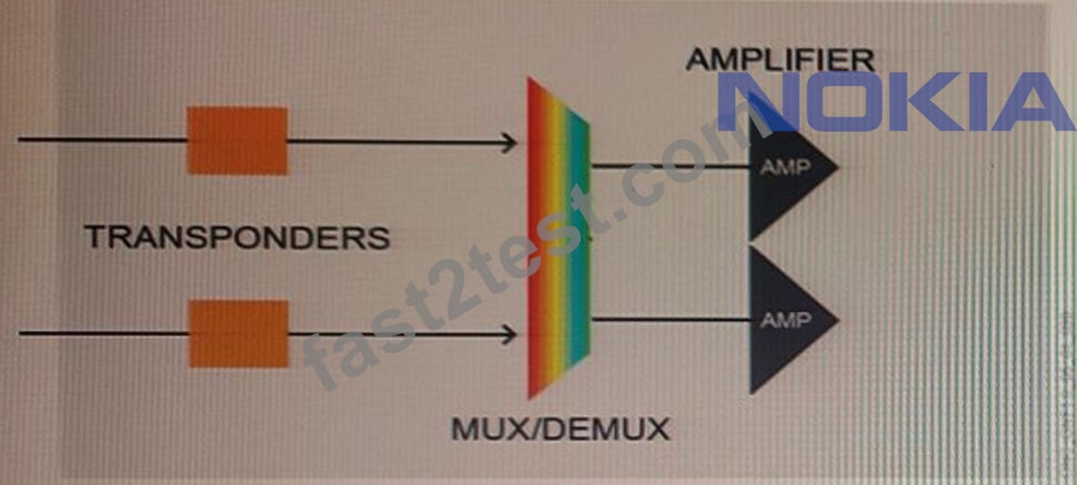
- A. Between the transponders and the mux/demux
- B. After the amplifiers
- C. Between the mux/demux and the amplifier
- D. Before the transponder, on the client side, towards the external device
Answer: D
NEW QUESTION # 32
Is it possible to modify node parameters within the edit EPT menu?
- A. Yes, the user can apply manual changes but only for non-GMPLS nodes, as the control plane reserves node resources not editable by the user
- B. Yes, but the user can modify only the node name and location
- C. Yes, the user can apply manual changes directly from this view
- D. No, this view is used to display a close-up view of the node
Answer: A
Explanation:
Yes, the user can apply manual changes but only for non-GMPLS nodes, as the control plane reserves node resources not editable by the user. The edit EPT menu allows the user to view information about a node but is not used to modify node parameters. The user can only apply manual changes to non-GMPLS nodes, as the control plane reserves node resources which cannot be modified by the user.
NEW QUESTION # 33
Which sentence about NFM-T is correct?
- A. NFM-T fully supports LO, LI, L2 and GMPLS applications and it is mainly focused on 1830 PSS, as well as other older product families
- B. NFM-T fully supports optical and IP nodes
- C. NFM-T is used to design and manage optical network
- D. NFM-T is used to provision optical services having IP nodes as extremities
Answer: D
Explanation:
NFM-T is a network management system designed to manage optical networks in a unified manner. It is used to design, manage, and provision optical services having IP nodes as extremities. It supports a variety of technologies, including optical and IP, and fully supports LO, LI, L2, and GMPLS applications. It is mainly focused on the Nokia 1830 PSS product family, as well as other older product families.
NEW QUESTION # 34
Where is the OPS card equipped to provide the optical channel protection?
- A. Before the transponder, on the client side, towards the external device
- B. Between the transponder and the filter
- C. Between the transponder and the amplifiers
- D. Between the filters and the amplifiers
Answer: C
Explanation:
According to the Nokia's 1830 Photonic Service Switch (PSS) product documentation, the Optical Protection Switching (OPS) card is equipped in the transponder and is responsible for providing optical channel protection between the transponder and the amplifiers. The OPS card monitors the optical signal and switches to a pre-configured protection path in case of signal degradation or loss.
NEW QUESTION # 35
......
Valid 4A0-205 Exam Updates - 2026 Study Guide: https://www.fast2test.com/4A0-205-premium-file.html
Top Nokia 4A0-205 Exam Audio Study Guide! Practice Questions Edition: https://drive.google.com/open?id=1lubhy-4yxScAe1UPqxbiDHy1n7hWaE3T